Understanding the rendering pipeline for Godot users
3D rendering is a complexe topic. Godot, as a game engine, does a great deal of effort to abstract and simplify that topic to be as user friendly as possible. Still, a lof of sections in the documention make much more sense when you really understand what's going on in your GPU. Here's what you need to understand about the rendering pipeline.
When you play a game, every 3D object in your scene — a character, a terrain, a particle effect — appears on screen as a flat image. To get there, the GPU works like an assembly line: raw data goes in (meshes, textures, material parameters) and pixels come out. Each piece of data passes through a fixed sequence of stages, one after another. That sequence is the rendering pipeline.
Low-level graphics APIs — like Vulkan, OpenGL, Direct3D, or Metal — expose the pipeline in full detail and require you to configure every stage yourself. Godot abstracts all of this: you place objects in a scene, assign materials, and the engine handles the rest.
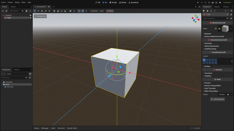
Still, a high-level understanding of what happens inside the GPU helps you in several ways:
- Abstractions are easier to work with when you understand what they abstract.
- Performance is easier to optimize when you understand where the GPU spends its time.
- Godot's rendering options — like spatial shader
render_modesettings — map directly to pipeline stages. Knowing the pipeline makes those options intuitive.
What you see on screen
A frame is a single game image displayed on screen. Games display many frames per second (often 60 or more) to create the illusion of motion. Each frame is a complete picture of the scene from the camera's point of view.
A mesh is a 3D surface made of triangles — it defines the shape of objects on screen. Characters, trees, buildings, and terrain are all meshes. Each triangle is defined by three vertices: points in 3D space. Every vertex carries data called attributes:
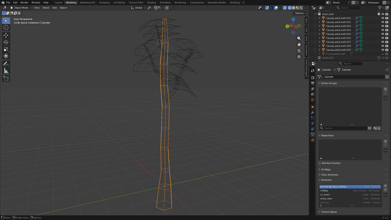
- Position — the vertex's location in 3D space, stored as three coordinates (x, y, z).
- Normal — the direction the surface faces at that vertex, used for lighting. A surface facing a light source appears bright; a surface facing away appears dark.
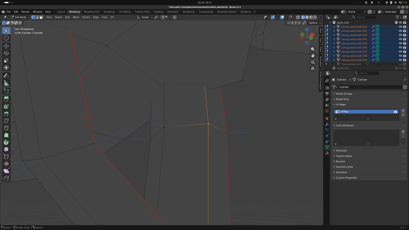
- UV — a 2D coordinate that tells the GPU which point in a texture image corresponds to this vertex. The UVs of a triangle's three vertices determine how the texture stretches across its surface.
The CPU and the GPU
Your computer uses two processors to produce each frame.
The CPU (Central Processing Unit) runs your game logic. In Godot, that means GDScript and C# scripts, physics simulation, navigation, animation, and scene tree management. Once the game state is up to date, the CPU prepares the rendering work: it collects the visible meshes, their materials, their positions, then sends all of it to the GPU.
The GPU (Graphics Processing Unit) contains thousands of small cores designed to run the same operation on many vertices or pixels at once. It receives that data and produces the frame.
The CPU and the GPU work in parallel. The CPU does not wait for the GPU to finish drawing a frame before it prepares the next one. This overlap keeps both processors busy and enables real-time performance.
Draw calls
To produce each frame, the CPU sends commands to the GPU. Each command says: "render these triangles, using this shader, these textures, and these parameters (transforms, colors, etc.)." That command is a draw call.
Godot issues draw calls automatically. Every frame, the engine walks through the visible objects in the scene and issues one draw call per material on each object. A character with separate materials for skin, hair, and clothing produces three draw calls. A typical 3D scene accumulates hundreds to thousands of draw calls per frame.
Each draw call costs CPU time to prepare and submit, so the draw call count is a key performance metric. You can see it in the Godot 3D editor (Perspective > View information).
The pipeline stages
Each draw call sends a set of triangles through a sequence of stages. Some stages run code that you can write or customize — that code is called a shader. Other stages are fixed operations performed by the hardware.
Here are the main stages:
- Vertex processing — converts each vertex from its 3D position to a 2D screen position (programmable: vertex shader)
- Rasterization — determines which pixels each triangle covers (fixed hardware)
- Fragment processing — computes the color of each covered pixel (programmable: fragment shader)
- Output merging — decides whether and how each pixel reaches the frame (configurable)
The rest of this page details each stage.
Vertex processing
The GPU runs the vertex shader once per vertex. A mesh with 300 vertices triggers 300 vertex shader runs — all executed in parallel.
The vertex shader's main role is to convert each vertex's position from its original 3D position to a final position on screen. This conversion goes through several coordinate spaces:
- Local space — the mesh's own coordinate system, centered on its origin. A 5m tree modeled in a 3D tool is defined in local space: the base of the trunk might be at (0, 0, 0) and the top at (0, 5, 0), regardless of where the tree stands in the game world.
- World space — the shared coordinate system of the entire scene. When you move a Node3D object in the editor, you change its world-space position. Three instances of the same tree mesh placed in a scene each have different world-space coordinates even though they share the same local-space geometry.
- View space (or camera space) — the coordinate system where the camera is at the origin. Every vertex position is measured from the camera: how far in front, how far to the side, how far up or down. The same tree placed 20 meters ahead of the camera has a view-space depth of 20, regardless of where the camera or the tree sit in world space.
- Clip space — the coordinate system that flattens the 3D scene into a 2D image. The camera's viewing angle and distance limits define a visible volume; everything outside that volume is discarded. Clip space still has a depth component — the GPU uses it later for depth testing — but the perspective effect is already applied: distant vertices are pushed closer together. After this step, the GPU converts clip-space positions to screen coordinates (pixel positions on the display).
The vertex shader is a complete program that transforms each vertex from local space all the way to clip space. It also forwards vertex attributes (normals, UVs, colors) to later stages.
In Godot, the engine handles the full coordinate transformation
automatically. Rather than writing a standalone vertex shader program, you
write a vertex() function that can modify vertex data before the
transformation — for example, offsetting positions each frame to animate a
waving flag. See Godot's Introduction to shaders for how Godot's shader
system works.
Rasterization
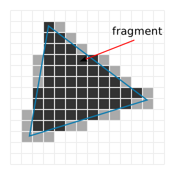
After projection, the GPU has flat 2D triangles in screen coordinates. The rasterizer checks which screen pixels each triangle covers. Every covered pixel becomes a fragment.
Rasterization is a fixed hardware stage — you do not write code for it.
The rasterizer also performs face culling: triangles facing away from the
camera are skipped by default, since they represent the back side of a
surface. In Godot, you can disable this with the spatial shader's
cull_disabled render mode.
The number of fragments the rasterizer produces directly drives the cost of the next stage. The same triangle seen from far away might cover only a handful of pixels and produce few fragments. Seen up close, it can fill a large part of the screen and produce millions.
Interpolation
The fragment shader expects attribute values (UVs, normals, colors) for each fragment, but those values are defined per vertex, not per pixel. The GPU interpolates them automatically: it blends each vertex's values based on the fragment's position within the triangle.
A fragment near one vertex gets values close to that vertex. A fragment at the center gets a roughly equal blend of all three. This is why a texture appears smooth across a triangle even though UV coordinates exist at the corners only.
Fragment processing
The GPU runs the fragment shader once per fragment. It receives the interpolated attributes and computes a color. This is where texture lookups, lighting, and visual effects happen.
The GPU processes thousands of fragments in parallel — this is what makes real-time rendering fast. Because of this parallelism, each fragment runs in isolation, with no access to neighboring fragments.
In Godot, the fragment() shader function handles this stage. Godot also
runs a separate light() function per fragment and per light for lighting.
Because screens contain far more pixels than meshes have vertices, fragment processing is usually the most expensive stage. A mesh with 500 vertices might cover 100,000 pixels on screen — each one triggers a fragment shader run.
Output merging
After the fragment shader produces a color, the GPU decides whether that fragment reaches the final frame. This happens through a series of tests, and results are written into the framebuffer.
A framebuffer is like a grid the size of your screen, where each cell corresponds to one pixel. Each cell stores several values:
- A color — the pixel's visible color on screen.
- A depth — how far the closest drawn fragment is from the camera.
The GPU uses these stored values to test each incoming fragment before writing it.
Depth testing. When a new fragment arrives, the GPU compares its depth against the depth already in the framebuffer. If something closer was already drawn at that pixel, the new fragment is discarded. Otherwise, it replaces the stored depth and color.
Depth testing lets opaque objects hide each other regardless of draw order.
In Godot, you can disable it with the spatial shader's
depth_test_disabled render mode.
Stencil testing. The framebuffer can also store a stencil value per pixel: an integer that shaders write to and test against. This enables masking effects — for example, only drawing a scene inside a portal's outline. In Godot, spatial shaders expose stencil operations through dedicated render modes.
Blending. For opaque objects, the fragment's color replaces whatever was in the framebuffer. Transparent objects work differently: their color blends with the existing color, weighted by an alpha value.
Transparency requires the GPU to draw objects back-to-front. The depth
test cannot help here — a transparent surface does not fully hide what is
behind it, so depth testing would discard fragments that should still be
visible. This sorting requirement makes transparent objects more expensive
than opaque ones. In Godot, spatial shaders control blending with render
modes like blend_mix and blend_add.
Once all draw calls for a frame are complete, the framebuffer holds the finished image. The GPU sends it to the display, and the process starts over for the next frame.
Key takeaways
-
A frame is one complete game image. The CPU and GPU work in parallel to produce many frames per second.
-
A draw call is a CPU command that tells the GPU to render a batch of triangles. Godot issues them automatically — roughly one per material per visible object.
-
A fragment is a pixel-sized sample of a triangle — not yet a final pixel. One screen pixel is built from one or more fragments.
-
Vertex shaders run per vertex. Fragment shaders run per covered pixel. Fragment shaders usually dominate rendering cost.
-
The depth buffer lets opaque objects hide each other automatically. Transparent objects bypass this and need back-to-front sorting.
-
Godot's
vertex()andfragment()shader functions map to the vertex and fragment processing stages. Many spatial shaderrender_modeoptions —depth_test_disabled,cull_disabled,blend_add— configure specific pipeline stages described on this page.
In the next articles of the serie, we will learn how to use Godot to program our gpu and how to best use it's performances.